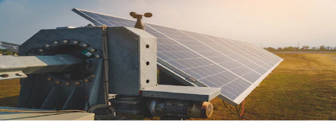

Solar panel tracking systems optimize energy output of photovoltaic panels by positioning them to follow the sun’s path throughout the day. The sun’s position in the sky varies both with installation location, the seasons, and the time of day. Tracking systems are being used increasingly as purchasers of solar systems understand that the cost of energy over the life of the panel is more important than the initial installed cost per watt.
This application note focuses on an algorithm and hardware to define the position of the sun as it moves through the day. Many of the function blocks created can be re-used in variety of types of solar tracker. To highlight some of these solar tracker types Horizontal-axis and Polar tracking have been identified.
Horizontal axis tracking: In horizontal axis tracking a long horizontal tube is supported on bearings mounted upon pylons or frames. The axis of the tube is on a North-South line. Panels are mounted upon the tube, and the tube will rotate on its axis to track the apparent motion of the sun through the day. Since these do not tilt toward the equator they are not especially effective during winter mid day (unless located near the equator), but add a substantial amount of productivity during the spring and summer seasons when the solar path is high in the sky. These devices are less effective at higher latitudes. The principal advantage is the inherent robustness of the supporting structure and the simplicity of the mechanism. Since the panels are horizontal, they can be compactly placed on the axle tube without danger of self-shading and are also readily accessible for cleaning. For active mechanisms, a single control and motor may be used to actuate multiple rows of panels.

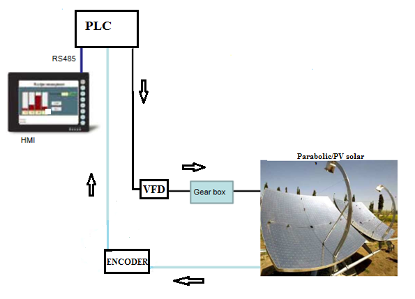
Two-axis mount tracking: Restricted to active trackers, one axis is a vertical pivot shaft or horizontal ring mount that allows the device to be swung to a compass point. The second axis is a horizontal elevation pivot mounted upon the azimuth platform. By using combinations of the two axes, any solar angle may be implemented. These systems require a PLC to determine the solar position to control the motor drives that orient the panels toward the sun.Since the solution for tracker control is based upon a PLC, an Analog to Digital Converter, a VFD and an HMI. The solution is mainly based upon the PLC which is primarily responsible for processing the algorithm to determine the sun’s position in a timely manner so that motor control can be implemented and interfacing sensory data and providing control signals to the VFDs to turn the arrays. The PLC is also responsible for controlling the solar arrays under high wind conditions and under excessive environmental temperatures. The VFD’s duty within the application is to control the position of the solar arrays and To enable simplified operator interaction with the solar tracking when setting parameters and monitoring the status of the application the solution features a HMI. The HMI is straightforward interfacing via serial link to the PLC and contains dedicated alarm handling to facilitate maintenance checks.Solar Position Algorithm: We have used the NASA/NERL Solar Position Algorithm. In the NERL SPA the Solar Position Algorithm (SPA) calculates the solar zenith and azimuth angles in the period from the year -2000 to 6000, with uncertainties of +/- 0.0003 degrees based on the date, time, and location on Earth. While NASA also created Algorithm to calculate the position of sun. The algorithm that has been implemented within the PLC to calculate the sun’s position. Unfortunately, a direct function will give a very long and difficult to compute equation, therefore intermediate steps have been used. Therefore, an algorithm using several different formulae, instead of a single formula has been used to calculate the position of the sun at a given date, time, latitude and longitude.
+91 9030070085
+91 7801063999
#501C, Bankers Chambers,
A S Raju Nagar, Kukatpally,
Hyderabad Telangana -500 072.